Dissecting Stereo Microscope Parts and Functions
Overview
Also known as a stereoscopic microscope, a dissecting microscope is a type of optical microscope commonly used for studying three-dimensional objects (3-D objects) as well as for dissecting biological specimen (e.g. insects and plant parts etc) at low magnification, between 2 and 100x depending on the microscope.
The main identifying characteristic of stereo microscopes is the fact that they contain two separate light paths with each of the light paths providing a different viewing angle. As a result, the user gets to observe three-dimensional images of the object under investigation.
This makes it the ideal tool for viewing the external features of relatively larger objects/specimen, dissection of biological specimen as well repairing circuit boards etc.
Main parts of a stereo microscope:
Parts and Functions of a Stereo/Dissecting Microscope
Stand/Arm
The stand/arm may be described as the "backbone" of the microscope given that it provides support to the head part of the microscope by connecting it to the microscope base.
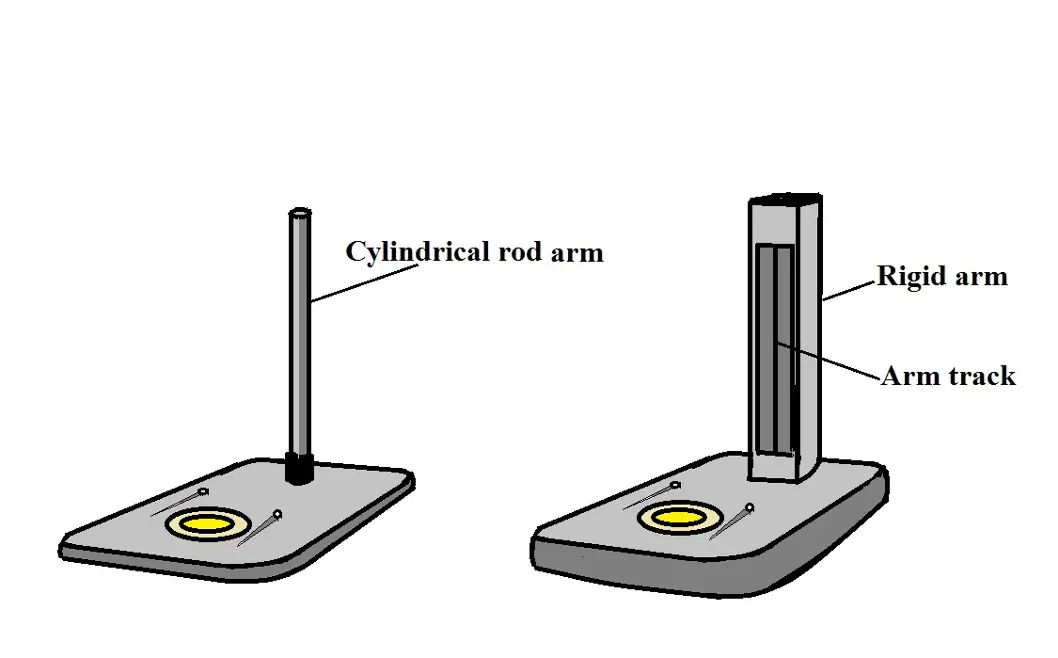
Depending on the microscope, the stand may either be a hollow, cylindrical rod or a rigid arm with a cuboid shape (elongated cuboid).
The power cord for incident illumination may be located, or originate from, the upper-most part of the stand allowing the specimen to be illuminated from above.
Apart from the power cord, the stand/arm may also consist of the arm track which allows the microscope head to be moved up and down during viewing (focusing). This feature is particularly common at the front part of a rigid arm.
Some of the main functions of the stand/arm include:
· Supporting the head - As mentioned, the stand is the "backbone" of the microscope that connects the microscope base to the head. As such, it holds the head in place even as it moves up and down during viewing.
· Focusing - On a rigid microscope stand/arm, the coarse focus knob is located on the stand. By turning this knob, the head is moved up or down allowing the user to focus on the object. On a hollow cylindrical rod stand, however, the knob is not directly located on the stand. Regardless, turning the knob allows the head to be moved up or down during focusing.
· Holds the power cord - For some dissecting microscopes, the stand/arm holds the power cord. Here, the cord is normally located at the top of the stand.
· Lifting/carrying - To carry, lift or move the microscope, it's often recommended that the user (students, technicians, etc) hold the tool by the stand/arm and the base. This is because the stand is sturdy and provides enough room for holding the microscope when moving or lifting it.
Base
The base is the lower part of the microscope that provides support to all the other parts of the microscope. It's wide and heavy thus providing stability when the microscope is placed on a table/working bench.
For some of these microscopes, the base may be bigger when compared to others. However, they serve the same functions.
The following are some of the main functions of the base:
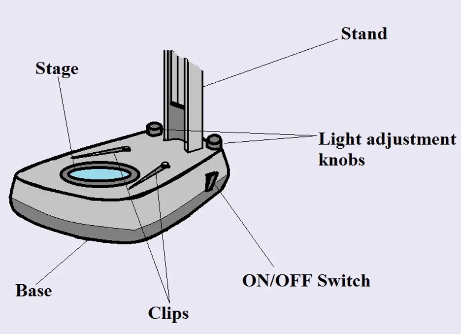
Stage - Unlike a compound microscope where the stage and the base are separate parts, the base of a dissecting/stereo microscope also acts as the stage. This is the part of the microscope on which objects/specimen is placed for viewing.
Depending on the microscope, the base may also consist of a pair of clips used to hold the specimen or slide in place. Here, the stage clips are located at the upper part of the base/stage directly below the objectives.
It's also worth noting that unlike the stage of a compound microscope, the base/stage of a dissecting microscope cannot be raised or lowered during viewing.
Support - As mentioned, the base is the lower, heavy part of the microscope that provides support for the entire device. This is the part of the microscope on which the stand is attached to hold the head in place.
The weight and width of the base provide the stability required to ensure that the microscope remains balanced during use. It ensures that the microscope does not tip over, topple or overturn.
Other parts of the stage:
In addition to some of its core functions (support and serving as the stage), the base also houses a number of other components that include:
· The on/off switch - The on/off switch may be located on the side of the microscope base (usually the right side). This is the part of the microscope used to turn the illuminator on or off. Before switching off the microscope, it's always important to first lower the light intensity.
· Light intensity regulator/control or the light adjustment knobs - Depending on the type of microscope, some dissecting microscopes only have the overhead light while others have both the overhead and stage light sources.
For microscopes that only have the overhead light source (where illumination is from above), then only a single light intensity control is present on one side of the stage. Using this control, the user can adjust intensity of the light and thus increase or decrease brightness or increase contrast, etc.
For microscopes with both the stage and overhead light sources, there are normally two light adjustment knobs that may be located opposite to each other behind the stand/arm on the base (or on the same side as the on/off switch).
One of the knobs is the overhead light adjustment knob while the other is the stage light adjustment knob. Like the light intensity regulator, the two knobs are also used for adjusting light intensity during viewing.
* The light intensity regulator is also known as rheostat light control.
Stage light - As mentioned, some dissecting microscopes have two light sources which include the overhead light and the stage light. For dissecting microscopes with two light sources, the stage light source is housed within the base. In this case, a clear glass plate is located above the light source so that it allows light to pass through and reach the specimen. The glass plate is usually held in place by a tight screw located at the central, front part of the base.
This type of illumination is generally used to view translucent specimen on a glass slide.
Lifting/carrying - As mentioned, the stage also allows the microscope to be lifted and moved safely. When carrying the microscope, students are advised to place one hand firmly below the base while holding the microscope by the arm with the other hand.
The two parts are sufficiently sturdy, allowing for the microscope to be moved without causing damage to any part of the microscope.
* For a dissecting microscope with an overhead light (illuminating the object from above), the source of light called incident illumination, is located on the body of the microscope behind the objectives.
For some microscopes, this source of light may come separately and is therefore not part of the microscope
Microscope Head
Also known as the body, the head is the part of the microscope that contains the upper optical part of the microscope. Apart from the optical parts, the head also consists of several moveable parts. For this reason, it's important to avoid holding the head when lifting the microscope to prevent potential damage to these parts.
The following are the main parts and functions of the microscope head:
Eyepieces
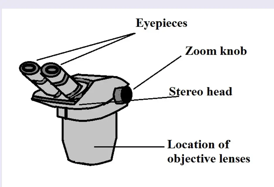
Also known as the ocular lenses, the eyepieces are the optical components of the microscope closest to the eyes - the part of the microscope through which the user looks into to observe the image of the object/specimen.
Although ocular lenses can also be found in a compound microscope, it's not possible to exchange these optical components between the two types of microscopes because of differences in diameter.
Essentially, the eyepiece is a magnifier that serves to magnify the image projected from the objective. As such, they help increase the size of the image to study details of the object under investigation.
The distance between the eye of the observer and the ocular lens at which the user can see the full field of view is known as eye relief. This distance is between 10 and 15 mm. This is particularly important in that it prevents eyelashes from affecting the field of view by coming into contact with the eyepiece lens.
For those who use eyeglasses, however, the distance can be increased to between 25 and 30 mm by adjusting the eyepiece eyeshields/eye-guards.
Depending on the type of eyepieces being used, some of the eyepieces (e.g. the aberration-free 10× eyepiece with diopter adjustment) have several lenses within the eyepiece including the eye lens, the lens doublet, the lens triplet, and the field lens doublet.
Simpler eyepieces may only consist of the eye lens and the field lens in place.
Usually, the eyepiece will have specifications to inform the user of the magnification the eyepiece provides among other features. For instance, the majority of the eyepieces provide a magnification of times ten (10). For this reason, the user can expect to see the 10× specification on the eyepiece.
Apart from magnification, some eyepieces may be labeled "WF" which indicates that the eyepiece provides a wide field of view. Essentially, this means that while viewing the object/specimen, the user will see wider areas compared to the field of view perceived using other eyepieces.
Some of the most common field numbers are 18 and 20mm. While neither increases the magnification nor the resolution, the wider field of view allows the user to see more.
* The diopter adjustment (located on the lower part of the eyepiece) allows the user to adjust one eyepiece and thus compensate for differences in vision between the two eyes when viewing through two eyepiece lenses.
One of the other important aspects of the eyepieces is the fact that it is possible to adjust the interpupillary distance (the distance between two eyepieces) in order to comfortably accommodate both eyes.
When adjusting this distance (By simply pulling apart or pushing the interpupillary adjuster close together), the goal is to ensure that the two field (the left and field fields) become one when looking through the eyepieces.
Once this has been achieved, then one can start adjusting other features (light intensity, magnification, focusing etc) for better viewing.
Objectives
The objectives are perhaps the most important component of a dissecting microscope as they are the main lenses that magnify the object and gather the light and produce the image seen on the ocular lenses. Like ocular lenses, the objective lenses of most quality microscopes are made of glass which is a superior material compared to plastic.
Compared to a compound microscope where the objectives attached to the nosepiece can be seen and identified individually (based on color bands and their respective labels), the objectives of a dissecting microscope are located in a cylindrical cone and are therefore not directly seen.
The cylindrical cone (in which the objectives are contained) can be turned to adjust the magnification.
There is also one objective lens for each of the eyepiece lens which results in the 3-D image produced when using this microscope. When in use, a stereo microscope may have two objective lenses in place with the magnification power ranging from 1x to 4x (1x, 2x, 3x, or 4x).
* Total magnification can be calculated by multiplying the magnification power of the objective lens to the magnifying power of the ocular lens.
Auxiliary lens
Source: Amazon:

Barlow Lenses
In addition to the objective lenses, some dissecting microscopes can accept accessories like Barlow lenses. Essentially, Barlow lenses are auxiliary lenses that can be used to increase or decrease the total magnification by a given factor.
For instance, whereas a Barlow lens with a magnification power of 2x increases the overall magnification, a Barlow lens of 0.5x will decrease the total magnification. This accessory can be easily installed on a dissecting microscope by simply mounting it into the threaded lens port (in the cylindrical cone that contains the objectives).
Here, the working distance has to be increased or decreased depending on the Barlow lens used. If a 0.5x Barlow lens is mounted, then the working has to be increased given that decreased magnification requires a longer working distance.
Higher magnification (by using the 2.0x Barlow lens) requires a shorter working distance and thus the microscope head has to be lowered.
Adjustment Knobs
Apart from the adjustment knobs located on the dissecting microscope base, there are other knobs located on the microscope head, body, or the stand/arm.
These knobs have different functions that include:
· Focus knob - Depending on the microscope, the focus knob (also known as the coarse knob) may be located on the stand/arm of the microscope, especially if the microscope has a rigid arm, or on the body of the microscope, common for microscopes with a hollow cylindrical rod. By turning this knob, the microscope head (and thus the objectives) can be raised or lowered increasing the working distance. By slowly turning this knob, it's also possible to bring the image into focus.
· Zoom knob - The zoom knob is located on both sides of the microscope head just below the eyepieces. Using the zoom knob, it's possible to zoom in on to a particular area of interest on the field of view to get a closer look.
While using the zoom knob, resolution may be affected. For this reason, the user may have to re-adjust the focus knob in order to bring the image into focus.
Other parts of a dissecting microscope:
The head/body of a dissecting microscope contains several important components that are hidden within the tube.
These include:
· Prism - bend light and thus change the orientation of the image
· Relay lens - serve to invert the image and also extend the imaging system
· Reticle - is a small piece of glass with a grid used for making measurements
How a Stereo Microscope is used
As mentioned, a dissecting (stereo or inspection microscope) is a low power microscope that is commonly used for the purposes of inspecting larger sized specimen/objects like fossils, rocks, insects, and parts of a plant, etc.
Here, however, specimen mounted on slides can also be viewed using this type of microscope. Depending on the type of specimen/object under investigation, a dissecting microscope can be used in a number of ways.
The following are some of the steps involved when using a dissecting microscope:
Before taking any step, it's important to note that depending on the microscope, the dissecting microscope may have two types of stages.
- The first type of stage may be an opaque black or white stage. This type of stage is commonly used for observing specimens/objects that are not transparent.
- The second type of stage is clear or frosted glass. This type of stage allows light from underneath to illuminate the specimen (particularly specimen mounted on a slide) so that light is then collected by the objectives just above the specimen.
Install the appropriate stage
Before switching the unit on, it's first important to change the stage to the appropriate one. If a stage is already there, then it can simply be removed by loosening the stage plate lock screw and replacing it with the appropriate stage.
If the stage is being replaced with a glass stage, a blue filter is usually inserted at the center of the base before placing it (glass stage) in place. Once the stage is in place, the stage plate locking screw is then tightened to ensure that it is held in place.
Ensure that light intensity is turned down to the minimum - This is an important step that protects and allows the bulb to last longer.
Turn on the unit/microscope
Using the on/off switch located on one side of the microscope base, turn on the microscope. Once the unit has been turned on, then the next step involves turning or switching on the incident or transmitted illumination (or both depending on the specimen).
Lower the head/body of the microscope
Using the focus knob (coarse focus knob), slowly lower the body/head, which holds the objectives, all the way to the bottom. This is particularly important given that it helps set a starting point.
Adjust the interpupillary distance
Looking through the eyepieces/ocular lens, gently pull them apart or push them close together/move them inwards or outwards (as one would with a pair of binoculars) and adjust them until one field of view is in focus.
Given that a specimen/object has not yet been mounted on the stage, the adjustment process should ultimately produce a single circle when viewing through the eyepieces - Therefore, in general, the interpupillary distance can only be said to be correct if the two fields of views that were initially observed (before adjustment) are unified and become one field of view following adjustment
Mount the specimen and focus
The next step involves mounting the specimen/object and focusing. Only the appropriate type of illumination is used for a given specimen.
For such organisms like Hydra (which has to be placed on a glass slide first), both the incident and transmitted illumination can be used for illumination. However, for an opaque object or specimen (e.g. a piece of rock, etc), then incident illumination is suitable for viewing.
Once the specimen has been placed at the central part of the stage (stage clips can be used to hold the glass slide in place if it is used), then focusing can start. This involves slowly turning the focus knob until the image becomes clear.
Given that the body/head of the microscope had initially been completely lowered, focusing would involve slowly raising the head/body using the focus knob until the image becomes clear.
Zoom in
Once the image is in focus by using the coarse focus knob, then the zoom knob can be used to zoom in to a given area of the specimen/object under investigation.
If a hydra is being viewed, then zooming can allow the observer to zoom in on the tentacles and get a better view of these structures.
Given that this may gradually distort the image causing it to become blurry, then the focus knob has to be used again to bring the image into focus.
* If necessary, light intensity can be adjusted using the intensity adjustments in order to increase or decrease the light intensity or simply to increase the overall contrast.
* At the end of the viewing process, it's always recommended that the zoom be set back to the lowest setting, light intensity be lowered and the microscope be turned off (using the on/off switch) and the microscope covered with the appropriate microscope/bag.
Check out MicroscopeMaster’s online help:
Basics of a Compound Microscope
Diagram/Parts/Functions of a Compound Microscope
Beginner Microscope Experiments
Microscope Slides Preparations-Styles and Techniques
Prepared Microscope Slides - Benefits and Recommendations
Return to Stereo Microscope main page
Return to Stereo Microscope Vs Compound Microscope
Return from Dissecting Stereo Microscope Parts and Functions to MicroscopeMaster home
References
Alan Hale. (2007). Microscopes.
Ki-Chul Kwon et al. (2010). High-Definition 3D Stereoscopic Microscope Display System for Biomedical Applications.
Robert N. Trigiano and Dennis J. Gray. (2016). Plant Tissue Culture, Development, and Biotechnology.
Samut Prakan. (2007). TRD 06: Stereomicroscope User Manual.
Links
Find out how to advertise on MicroscopeMaster!

